
Many machine shops drastically underestimate the machinability of brass and as a result run it as much as 85 percent slower than is actually possible with today’s advanced machine tools. However, once shops abandon these outdated, overly conservative assumptions, they can machine brass at higher speeds and feeds to increase part productivity. But before they put tool to part, shops must give careful consideration to certain aspects of set up that include tools and inserts, spindle liners and G-code to unlock the true high-speed machining capabilities of brass.
1. Choose the appropriate tools and inserts.
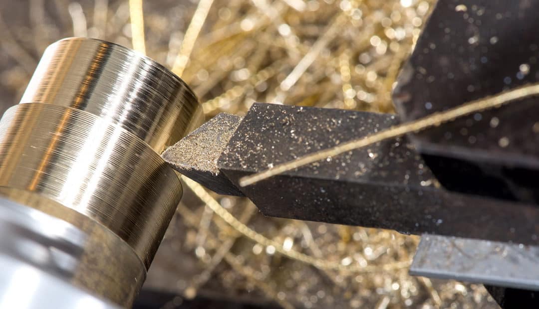
To work effectively with brass, use carbide cutting tools or tools with carbide inserts to ramp up material removal rate (MRR) and allow milling machines to run at higher speeds and with longer tool life. Production testing shows that carbide cutting tools operate with virtually no wear for longer periods of machining at up to 4,000 SFM, completely outperforming what high-speed steel tools can accomplish.
2. Add spindle liners to protect operators, equipment, material and parts.
To work safely and productively at higher RPMs when machining brass on modern bar fed turning machines, use a spindle liner – also known as a filler or reduction tube, a draw-tube sleeve or a master liner – to reduce the clearance between the outer diameter of the bar stock and the inner diameter of the draw tube. Especially at spindle speeds above 3,000 to 4,000 RPM, a properly designed spindle liner fits inside the draw tube and protects working stock from scratches. Liners also reduce clearance to damp vibration and eliminate the phenomenon of bar whip for faster machining speeds, higher-quality parts, safer operations and lower noise levels.
3. Use the right G-code to set spindle speed for best results.
In the G-code programming language used with CNC machining equipment, code G96 invokes constant surface speed mode. Like auto exposure on a camera, in which the equipment calculates how long to open the shutter based on the amount of light available, constant surface speed mode automatically sets spindle RPM based on tool diameter. Conversely, code G97 sets RPM mode, for which an operator must calculate surface speed manually. RPM mode requires an objective assessment of how fast a job can run, not just an estimate.
For brass machining, correctly set RPM modes can speed up cycle times, especially on parts without large changes in diameter. This requires a full understanding of the formula for calculating spindle speed and the relationship between spindle speed and cycle time. Otherwise, simply guessing at the correct speed can yield poor surface finishes and shortened tool life. Of course, RPM mode becomes a necessity, not a choice, for center cutting, threading and live tooling, and with unbalanced workpieces that are unable to rotate properly at high speeds.
Recent Comments